Edit
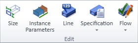
On the Ducting tab, the Edit group includes the following tools.
Size of part

You can modify the dimensions of a single straight duct part or duct component. Depending on the part, the parameters to modify can be:
-
The diameter of a round duct part.
-
The width and height of a rectangular duct part.
-
Shape parameters defined in the duct part design rule.
Tip: You can also use the Size of run command to modify a single duct part that does not use instance parameters.
Prerequisites
-
The cross-section is not fixed.
Do the following:
-
Select Ducting tab > Edit group > Size of part.
-
Select the duct part in the model and press Enter.
-
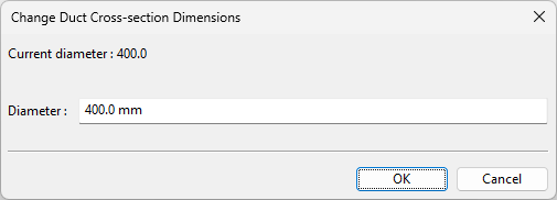
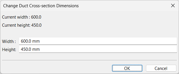
If the duct part has no instance parameters or design rules, the Change Duct Cross-section Dimensions dialog opens. Enter the new Diameter or Width and Height, and click OK to apply the change.
-
If the duct part uses design rules but does not use instance parameters, the 'Apply Duct part design rule' dialog opens. Edit the parameters as required and click OK to apply the change.
-
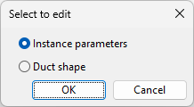
If the duct part uses both design rules and instance parameters, you are prompted to select which ones to modify.
-
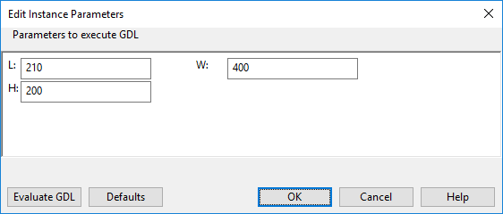
If you choose Instance parameters, the Edit Instance Parameters dialog opens. Edit the parameters as required (click Defaults to restore default values, if needed), click Evaluate GDL to check the results, and click OK to apply the change.
-
If you choose Duct shape, the 'Apply Duct part design rule' dialog opens. Edit the parameters as required and click OK to apply the change.
-
Size of run

You can modify the cross-section of a set of connected duct parts at one go. The duct run to resize can include straight duct parts and duct components. If straight parts contain onto-line components, those components are resized accordingly.
This function does not support instance parameters. If it encounters a duct part that uses instance parameters, execution stops and you are prompted to either accept or revert the changes that were made up to that point.
Although the command is intended for resizing an entire duct run, it can also be used on a single duct part. When used on a single part, all editable dimensions can be modified.
Prerequisites
-
The cross-section is not fixed.
-
The first and last part are the same size.
-
No branch nodes are connected.
Do the following:
-
Select Ducting tab > Edit group > Size of run.
-
Select the first part and press Enter, then select the last part and press Enter.
(To modify a single part instead of a run, select that part and press Enter twice.)
-
If prompted to select a reference point for the adjustment, select the required point from the on-screen tool, and press Enter.
-
If the duct part does not use design rules, the Change Duct Cross-section Dimensions dialog opens. Enter the new Diameter or Width and Height, and click OK to apply the change.
-
If the duct part uses design rules, the 'Apply Duct part design rule' dialog opens. Edit the parameters as required and click OK to apply the change.
Line

You can change the system or line of one or more straight, rectangular air duct parts or ducting components.
Do the following:
-
Optionally, select the new system or line from the Model Tree pane.
-
Select Ducting tab > Edit group > Line. The Select Ductline and Specification dialog opens.
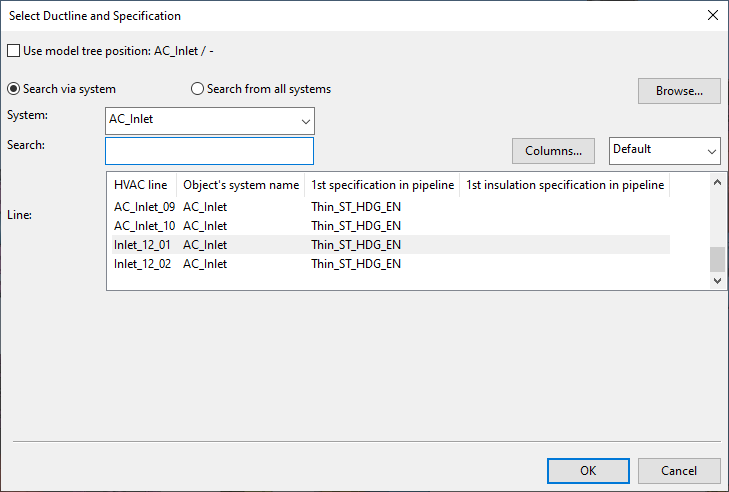
-
Select Use model tree position… if you already made the appropriate selection in the Model Tree pane. Otherwise, select the system and line to use.
You can use the Search field to find the required line. Also regular expressions are supported.
 Show/hide details
-
The columns that are searched are predefined. Note that the search string can also be found from a column that is not currently visible: click Columns to define which columns to show.
-
The search string can be found from any part of the target string, and the search is not case-sensitive.
Search string…
Finds…
line
strings that contain LINE, such as 'MyLine-01'
-
You can use a dot to represent a single required character.
Search string…
Finds…
....line-01
strings where LINE-01 is preceded by at least four characters, such as 'AA_MyLine-01'
-
You can use advanced regular expressions if you add R: to the beginning of the search string.
Search string…
Finds…
R:[ad]
strings that contain A or D, such as 'DIN_H2A'
R:[a-d]
strings that contain A, B, C or D, such as 'CW-001'
R:^k
strings that start with K, such as 'K51'
R:[\s]
(or just R: followed by one space character)
strings that contain a whitespace character, such as 'My Line 01'
-
-
Click OK.
Specification
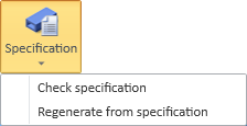
On the Ducting tab, in the Edit group, the Specification menu includes the following tools.
Check specification | Regenerate from specification
Check specification
You can check the specification status of air duct parts. You can use this tool even if the parts are not checked out to you.
Tip: If you want to change the specification that a duct part uses, use the Set Spec tool in the Spec Manager dialog, as described in Regenerate from specification.
Do the following:
-
Select Ducting tab > Edit group > Specification > Check specification.
-
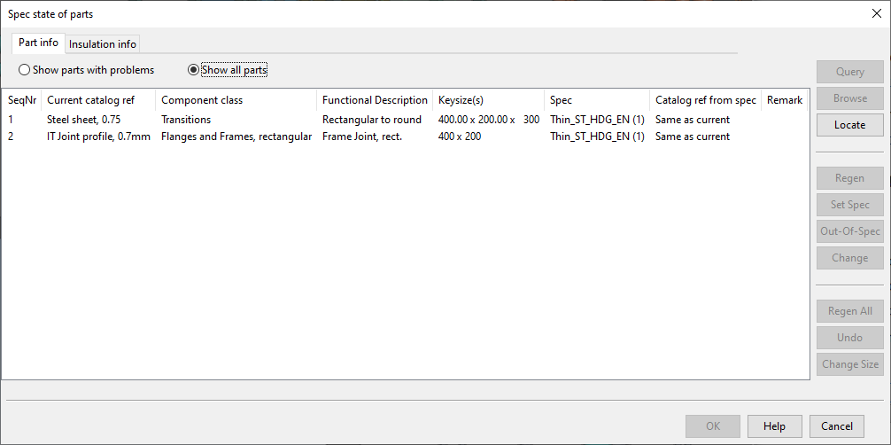
Select one or more air duct parts from the model and press Enter. The Spec state of parts dialog opens, displaying the specification status of the selected parts.
-
In this dialog, besides reviewing the statuses, you can only do the following:
-
Query – Select one or several parts from the list and click Query to open the Object properties dialog for each selected part.
-
Browse – Select one or several parts from the list and click Browse to see where the parts are in the model. Pressing Space moves the focus to the next selected part and after the last part reopens the Spec state of parts dialog.
-
Locate – Click Locate, select a part from the model, and press Enter to highlight that part in the Spec state of parts dialog.
-
-
Click Cancel to close the specification status dialog.
Regenerate from specification
You can manage duct parts by changing their ducting specification or insulation specification, by regenerating them so that they match their specifications, by marking them as out-of-specification, or by changing their Catalog Part reference.
Prerequisites
-
The objects to be modified are checked out to you.
-
Make sure that you have at least one work view where you can clearly see the duct parts that you intend to modify, but not too many shaded views open at the same time. This is because selecting a part in the tool highlights the corresponding duct part in all open views, and updating many views at the same time can affect the refresh rate and make the tool less responsive.
Do the following:
-
Select Ducting tab > Edit group > Specification > Regenerate from specification.
-
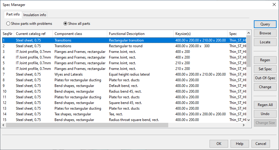
Select the required parts from the model and press Enter. The Spec Manager dialog opens, showing the selected parts ordered by their runs.
There are two tabs: Part info shows information on the part itself, and Insulation info shows information on the part's insulation.
On each tab you can select either Show parts with problems or Show all parts, depending on what you want to see.
The columns that show the system and the ductline of each part are visible only if you have selected parts that belong to different systems or ductlines.
-
You can use the following tools:
-
Query – Select one or several parts from the list and click Query to open the Object properties dialog for each selected part.
-
Browse – Select one or several parts from the list and click Browse to see where the parts are in the model. Pressing Space moves the focus to the next selected part and after the last part reopens the status dialog.
-
Locate – Click Locate, select a part from the model, and press Enter to highlight that part in the Spec Manager dialog.
-
Regen – Regenerates the selected parts.
The program uses the current key size, specification, and functional description to find the given part from the specification and check what its Catalog Part should be. Then the duct part is set to use the intended Catalog Part.
For shapes and straights, changes in material thickness cause any attached parts to move correspondingly.
For components (fire damper), change in length makes the connected duct parts to adapt to this, provided that there are enough straight parts around to absorb these changes. Changes will be applied to neighboring parts even though they are not in the set of parts that you are managing in the Spec Manager dialog.
You cannot perform this on the Insulation info tab if the selected parts are not insulated.
-
Set Spec – Depending on the tab you are in, this command opens either the Select Spec or Select Insulation dialog where you can change the specification that the selected parts use.
You can only choose a specification that is assigned to the line in question.
After the specification has been changed, the parts are regenerated.
If you are changing the insulation specification, also “No insulation” is an option.
Tip: You can also change the specifications during duct routing, using the commands Change specification and Change insulation specification, respectively. See Ducting context menu.
-
Out-of-Spec – Marks the selected parts as out-of-spec parts. You can use this to disassociate a part from its current specification. This is available only if the line definition of the part allows out-of-spec parts.
This operation should be used very cautiously, as most of the editing operations that target duct parts rely on information that is looked up from the specification. If you break this association, then you can no longer insert flanges to ducts, for example.
-
Change – Opens the Select Component dialog where you can change the Catalog Part reference of the selected parts.
You can use this, for example, when there are two different definitions for a fire damper in the same specification, and during routing you have added the shorter damper, but later you want to change it to the longer one.
If you apply this command to a duct part that is defined via shape, then you can also edit the shape parameters. Note that you cannot change the shape that the part is currently using—only its parameters. You can change the design rule that controls the parameter values, but still the shape type for which the design rule is made needs to be the same as that used in the part.
-
Regen All – Regenerates all the parts, without you having to select them from the list.
-
Undo – Reverts the latest change.
-
-
Click OK to close the dialog.
Flow

On the Ducting tab, in the Edit group, the Flow menu includes the following tools.
Check direction of flow | Set direction of flow
Check direction of flow
You can check what is the current flow direction in each connection node of an air duct part. If you find conflicting directions, you can use the Set direction of flow tool to correct them.
Do the following:
-
Select the Ducting tab > Edit group > Flow > Check direction of flow.
-
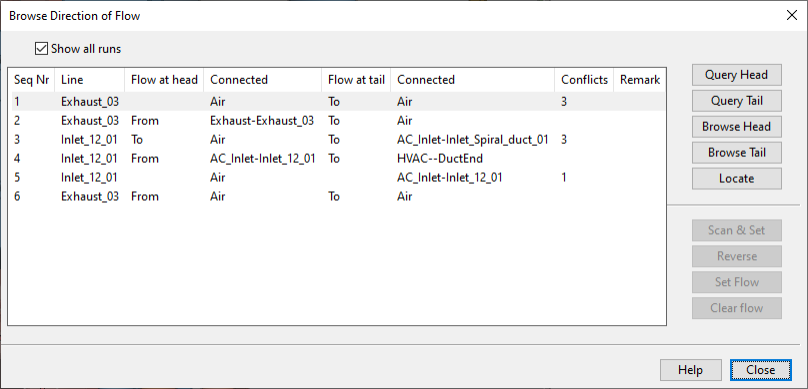
Pick one or more duct parts from the model and press Enter. The Browse Direction of Flow dialog opens, listing the duct runs of the picked parts and information about them.
-
If you want the list to show only those runs that have conflicts, clear the Show all runs option.
-
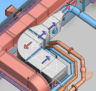
Select one or more duct runs from the list. The related objects are highlighted in the model and arrows indicate the current flow directions.
-
You can use these commands to get information about the selected runs:
- Query Head – Opens the Object properties dialog to display information about the head part of the run.
- Query Tail – Opens the Object properties dialog to display information about the tail part of the run.
- Browse Head – Opens the active work view with the cursor placed at the head of the run.
- Browse Tail – Opens the active work view with the cursor placed at the tail of the run.
- Locate – Allows you select a duct run from the list by picking one of its parts from a work view.
-
Click Close to close the Browse Direction of Flow dialog.
Set direction of flow
You can set, change, or remove flow direction in each connection node of an air duct part.
Do the following:
-
Select the Ducting tab > Edit group > Flow > Set direction of flow.
-
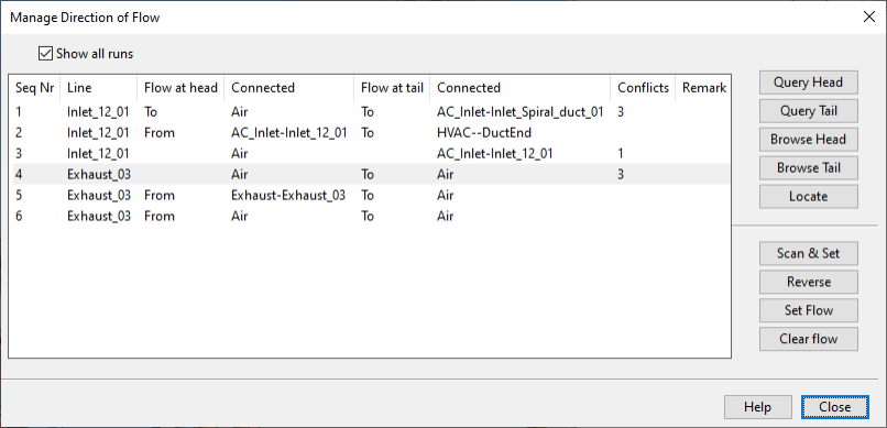
Pick one or more duct parts from the model and press Enter. The Manage Direction of Flow dialog opens, listing the duct runs of the picked parts and information about them.
-
If you want the list to show only those runs that have conflicts, clear the Show all runs option.
-
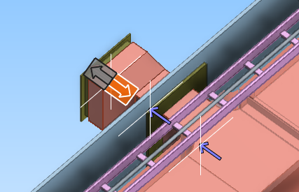
Select one or more duct runs from the list. The related objects are highlighted in the model and arrows indicate the current flow directions.
-
You can use these commands to get information about the selected duct runs:
- Query Head – Opens the Object properties dialog to display information about the head part of the run.
- Query Tail – Opens the Object properties dialog to display information about the tail part of the run.
- Browse Head – Opens the active work view with the cursor placed at the head of the run.
- Browse Tail – Opens the active work view with the cursor placed at the tail of the run.
- Locate – Allows you select a duct run from the list by picking one of its parts from a work view.
-
You can use these commands to manage the flow directions of the selected duct runs:
-
Scan & Set – Starts an interactive tools that prompts you to set the flow direction of each connection in the selected runs by clicking the appropriate end of the two-headed arrow.
-
Reverse – Reverses all flow directions in the selected duct runs.
-
Set Flow – Shows the flow direction of the selected duct runs and allows you to change their flow direction, one connection node or an entire run at a time.
-
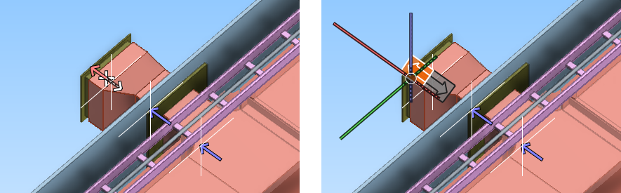
Set flow direction for a single connection point:
-
Pick the connection point whose flow direction you want to change, and accept the selection.
-
Press Esc, and then select the new flow direction by clicking the two-headed arrow.
-
Press Esc to return to the Manage Direction of Flow dialog.
-
-
Set flow direction for a duct run:
-
Pick the connection point at one end of the run, and press Enter.
-
Pick the connection point at the other end of the run, and press Enter.
-
Select the new flow direction for the whole run by clicking the two-headed arrow.
-
Press Esc to return to the Manage Direction of Flow dialog.
-
-
-
Clear Flow – Shows the current flow directions of the selected duct run. Select the connection whose flow direction you want to remove and press Enter to accept the removal.
You can continue removing other flow directions in the same way. Press Esc to return to the Manage Direction of Flow dialog.
-
-
Click Close to close the Manage Direction of Flow dialog.